Ideal photo voltaic cell

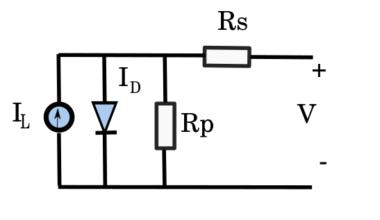
For better understanding, abstract ideal photo voltaic cell can model represent a parallel connection of ideal current sources and diodes since it is lighted photo voltaic and functions as a continuous current source by definition, which helps us better grasp the fundamental characteristics of photo voltaic cells. Add a parallel resistace Rs to this model’s and series resistances Rs to create a realistic solar cell that takes into account losses when calculating power
within the cell itself. The model is applicable to all classes of solar cells. The current-voltage characteristic of a photo voltaic cell is given by relation:

Lorem ipsum dolor sit amet, consectetur adipiscing elit. Ut elit tellus, luctus nec ullamcorper mattis, pulvinar dapibus leo.
- I – Current through PV module connections
- V – Voltage at the connections
- IL Generated current of the photocell (depends on the radiation intensity)
- Io -the dark current saturates the PV cell
- Rs -Series resistance of the PV cell
- Rp – Parallel resistance of the PV cell
- e – elementary charge
- n – ideality factor
- k -Boltzmann constant
- T -0K temperature
Now lets take look on some important properties that influence on efficiency….
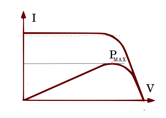
Currents and Voltage, basic I-V and P-V diagrams
A photo voltaic cell’s non-linear I-V and P-V properties are highly dependent on environmental variables including temperature and the amount of solar energy it receives. These properties are also influenced by the parallel and series resistances (Rs and Rp) that each cell possesses.
The maximum amount of power P that a solar cell may produce depends on the operating parameters (voltage V and cell
current I). Energy should always be used in points of maximum power, or MPPs (Maximum Power Points), in order to achieve maximum usage .

Series Resistance Rs
The material and manufacturing procedure used to create solar cells determine the series resistance Rs, which should ideally be as low as possible. The ohmic resistance that the flowing current encounters is known as serial cell
resistance is the ohmic resistance encountered by the flowing current through the cell, and then through ohmic contacts on the surface of the cell to the external circuit. For common solar cells, the product of the series resistance and cell area is on the order of 0.0025 [/m2]. A large Rs causes the photo voltaic cell to behave like a resistor because increasing the series resistance lowers the voltage at the solar cell terminals, which results in a current drop and a reduction in the current-voltage slope characteristics.
Parallel resistance Rp Shunt
The parallel resistance (shunt) Rp is determined by the cell’s characteristics and is usually large enough to be ignored. Originates from micro defects and impurities inside the solar cell. Parallel resistance cell Rp is caused by local defects in the p-n junction. In an ideal cell, it would be infinite; however, in each real cell, the current losses are proportional to the voltage. In the equivalent scheme of the cells, the current losses are shown by the parallel resistance Rp. If the parallel resistance decreases, a larger current flows through it, so for the same voltage, there is a smaller current in the solar cell connections. If the parallel resistance is even higher, then the photo voltaic voltage will decrease significantly, so it will behave similarly to a resistor
PV Cels Connections
Depending on the requirement, we can connect the cell in parallel or series to achieve the desired voltage or current. A larger number of connected photovoltaic cells make a photovoltaic panel.
The module serves as the attachment point for the cells and provides protection against atmospheric influences. The photovoltaic model is realized on panels through the use of multiple connected single diodes connected in series. Silicon is the main semiconductor element in the production of photovoltaic cells. Silicon belongs to the IV-group of the periodic system of elements. You can easily obtain and process silicon, and it doesn’t create any harmful compounds for the environment. With oxygen, silicon creates SiO and SiO2, which are dielectric materials. In terms of structure, silicon can be amorphous, polycrystalline, or monocrystalline, resulting in three types of silicon photovoltaic cells. These structures flow through silicon, resulting in a smaller current in the solar cell connections at the same voltage. If the parallel resistance is even higher, then the photovoltaic voltage will decrease significantly, so it will behave similarly to a resistor.
Depending on the need, one can connect the cell in parallel or series to obtain the appropriate voltage, or the cell’s current. A photovoltaic panel (module), which attaches and protects the cells from atmospheric influences, consists of a larger number of connected photovoltaic cells. The photovoltaic model is realized on panels through the use of multiple connected single diodes in series. Silicon is the main semiconductor element in the production of photovoltaic cells. Silicon belongs to the IV-group of the periodic system of elements. You can easily obtain and process silicon, and it doesn’t create any harmful compounds for the environment. With oxygen, silicon creates SiO and SIO2, which are dielectric materials. In terms of structure, silicon can be amorphous, polycrystalline, or monocrystalline. You can find more details on …>.
Conclusion
The efficiency of photo voltaic solar cells ranges from several percent to 40%, and most often within the limits of 10% for cheaper versions with amorphous silicon and up to 25% for more expensive ones. Monocrystalline silicon cells have a utility
factor of about 24%, polycrystalline silicon cells have a utility factor of about 15%, and amorphous silicon cells have a utility
factor of about 10%. The remainder that is not converted into electricity is mostly converted into heat, which thus warms the cell. In general, the rise in temperature of a photo voltaic solar cell leads to a reduce its efficiency.
Read about it on Wikipedia

