
The size of our previously calculated solar array is the main factor in determining the size of the solar inverter. A solar inverter with sufficient capacity should convert the solar arrays’ DC electricity into AC electricity.
The key element for configuring the system is fitting the modules into the available space, in case the space is limited by the roof of the house. If the panels are placed on a flat surface, then we have more maneuvering space.
Panel wiring methods
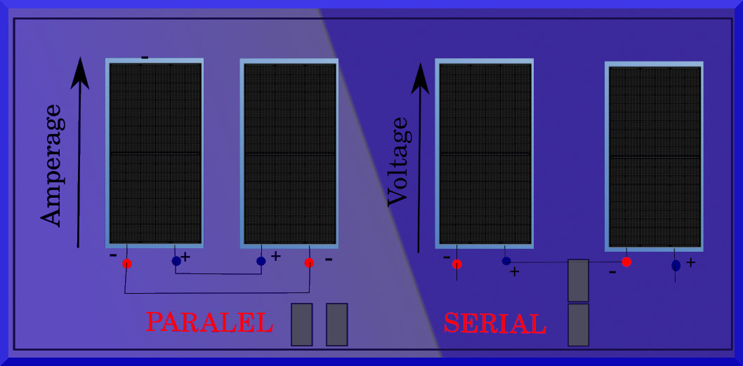
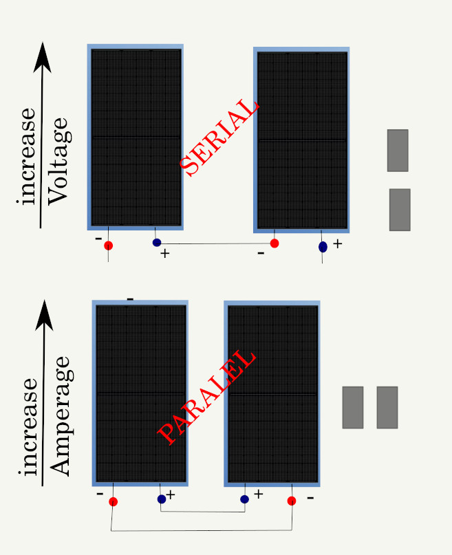
Solar Panels can be connected in series, parallel, or combined (hybrid).
Serial (in-line) connection is the case where the modules are connected one behind the other, the plus pole of the first panel to the minus pole of the second panel, and so on to the last one. With this connection, the current remains constant while the voltage is increased. The following equations explain:
I = Isc = const.. while V = Vsc1+ Vsc2 +… Vscm,
where m is the total number of panels in the series.
Important note: A serial connection is the most common case that dealers offer in ready-made configurations.
Parallel connection is when the panels are connected so that the plus poles of the panel are connected to one point and the minus poles to another. In this way, the current increases while the voltage remains constant. The following relationship explain :
V= Vcs while I = Isc1+ Isc2 + Isc3 +… Iscn,
where n is the total number of panels (connected in parallel).
A combined (hybrid) connection is a combination of parallel and series-connected panels and is used to increase current and voltage. All connections are necessary to allow proper DC current input to the inverter.
Various combinations of solar panel wiring
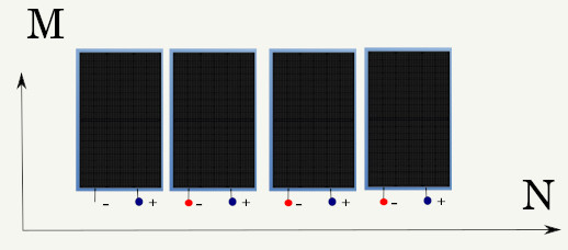
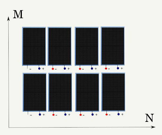
Solar panels can be connected in series, parallel, or combined. It is very important that the panels form an MxN matrix that depends on the number of panels. If you need to connect a large number of inverters, none of them must stick out; that is, they should all be connected in a quadrilateral matrix MxN, where M-number of panels connected in series M = 1,2,3 …. N is the number of panels connected in parallel; N = 1.2.3,,,,
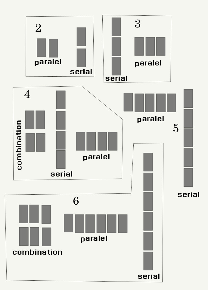
Here are some examples if we have:
2 panels are possible in only 2 combinations, connected in parallel or in series.
3 panels can be connected in series or in parallel.
4 panels can be connected in series, in parallel, or in a combined 2×2 grid.
5 panels: possible to connect only in series or only in parallel
The rule states that we can connect an odd number of panels that are not divisible by odd numbers either in series or in parallel. For instance, the 23-panel configuration that retailers frequently offer has sequential connections. We will consider this configuration for a 10-kW system. Another example is that 25 panels can be connected and combined in a 5×5 grid, etc.
Analysis of internal series-parallel connections of modules
The basic mathematical model for the calculation will be the grid of panels [M x N], where M is the where is :
M: number of rows or nuber of serial connections
N: number of columns or number of parallel connections
For this purpose, we adopt the Cartesian coordinate system where M is the abscissa and N is the ordinate. Output voltage at the maximum power point :
V = M*Vpmax. and I = Isc * N
The resulting value should fit into the DC voltage range of the inverter. More precisely, this voltage should fit into the DC voltage range of the lower-to-upper voltage value, which is required by the available inverter, but be as close as possible to the nominal value of the input DC voltage.
If the voltage is very close to the lower limit, you should consider choosing a smaller inventory or repacking the rows of panels, because when the modules heat up above the standard temperature, the voltage will drop, so it is realistic that it will also drop below the lower voltage value, which is not good from the aspect of the inverter. For this reason, the aim is for the voltage to be approximately close to the recommended value, which provides good conditions for the operation of the MPPT system and the inverter itself.
It is important to calculate the maximum voltage that can appear on the solar connection panels. The maximum voltage occurs when the circuit is unloaded and the temperature is low. If you choose the lowest temperature during the day at the analyzed location (the program does it by itself based on the selected city) and assume that the temperature of the solar cells is the same as the ambient temperature, then the maximum open circuit voltage at the module connections is:
Voc.max = Voc(stc) * (1+ Kt *ABS (Tmin + Tamb)
T min is the minimum temperature that can occur. T amb: ambient temperature Voc: open circuit voltage (summed) Kt -thermal Pv module coeficient
Then the calculated maximum voltage should be compared with the maximum tolerated voltage at inverter connections, and it should be concluded whether the selected PV panel is satisfactory in terms of maximum voltage.
Mismatch in PV Modules connections
is very important that all solar panels be from the same manufacturer and have the same characteristics. In the case of a series connection and different panel characteristics, the total power will drop depending on the current of the weakest panel; the voltage will not be significantly affected, but the current strength will be as much as the weakest panel can generate. If panels of different configurations are connected in parallel, an analogous behavior will occur. This time the voltage will drop according to the Uvoc or Uppmax of the weakest panel.
How to choice inverter
The choice of inventory depends on the power and number of panels we plan to install. First, multiply the number of solar panels. Sum = M*N; it’s hot. M: number of rows; N: number of columns. Then we multiply the number of solar panels with the declared power. The next step is to select the inventory of the first higher power than the obtained value. In the case of a solar power plant with a higher capacity, Sum > Sum max, a larger number of inventors is needed. Then we will divide the power plant into smaller segments that correspond to the above conditions. However, for an ordinary user who does not plan to sell green energy, we can ignore this for now. Once we have determined the power of the inverter, it is necessary to adjust the input voltage so that it targets the nominal voltage of the inverter in order to make the best possible use of it. And finally, determine the current strength, which must not exceed the value of the input current strength, which must be lower than the one required by the inverter.
more about PV module wiring can be read there
Using the SPAC application for inverter selection
After selecting all the parameters for the calculation of the electricity you can get on your property, further calculation is possible by choosing the offered inverters for the power class of the calculated and selected solar panels. Simply select the inverter offered by the application for your solar panel configuration, and the program will provide all combinations and calculations of voltage and current with recommendations on how to connect the panels most advantageously.
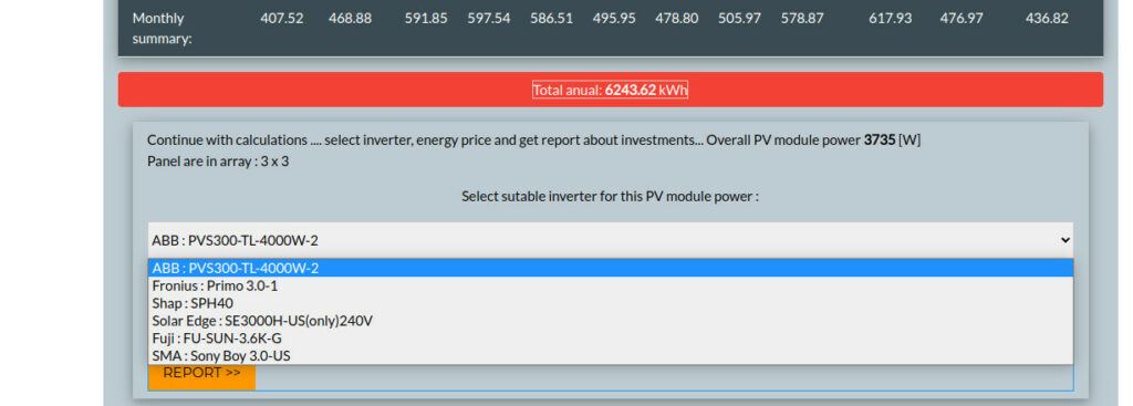
For example : We have an array of 3×3 solar panels with 490 W installed in the Port Sudan area. The panels are oriented to the south with a 20-degree slope. For this configuration, we have a recommendation for six grid-tied inverters.